Inverse rendering seeks to recover 3D geometry, surface material, and lighting from captured images, enabling advanced applications such as novel-view synthesis, relighting, and virtual object insertion.
However, most existing techniques rely on high dynamic range (HDR) images as input, limiting accessibility for general users.
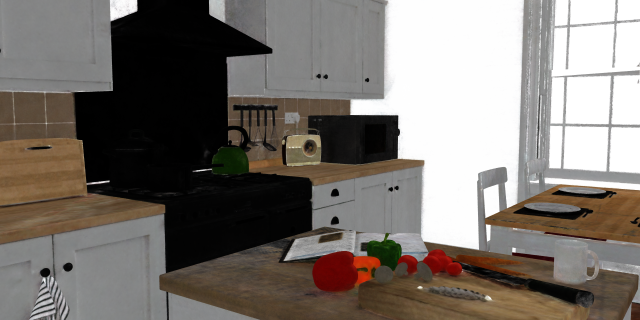
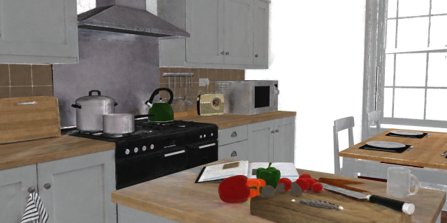
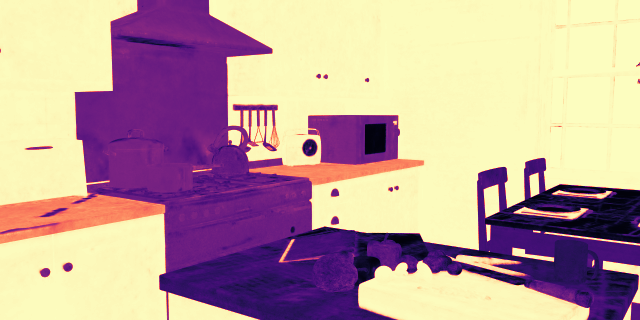
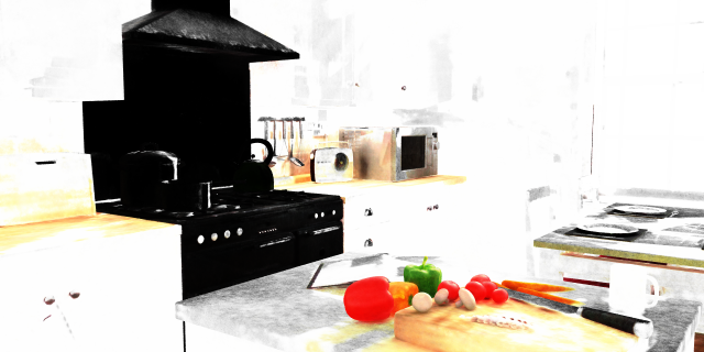
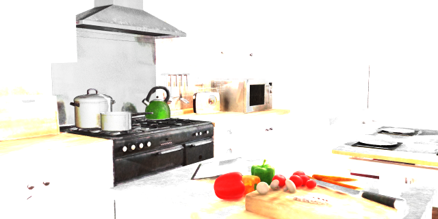
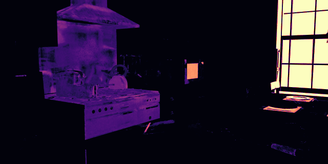
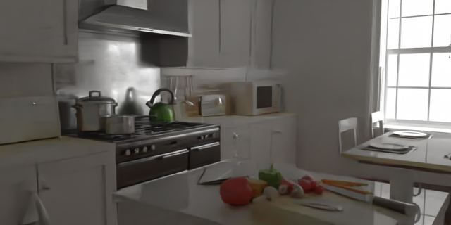
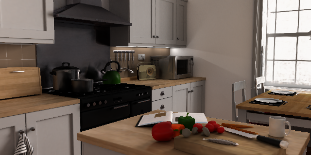
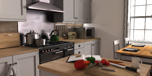
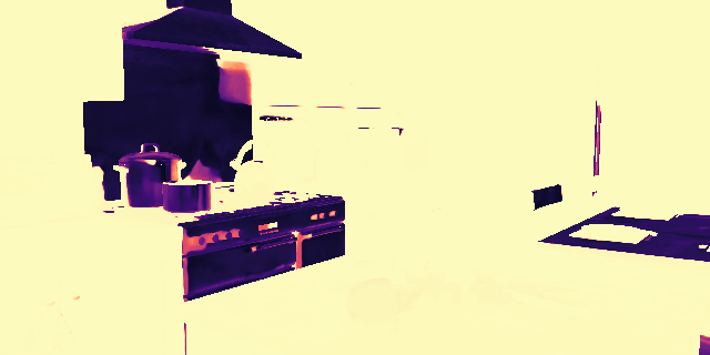
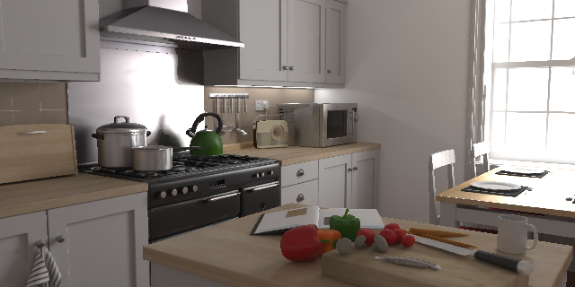
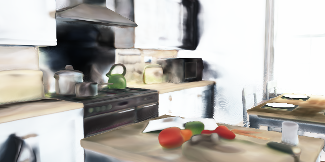
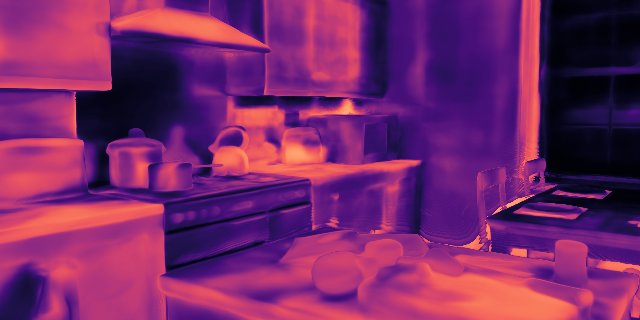
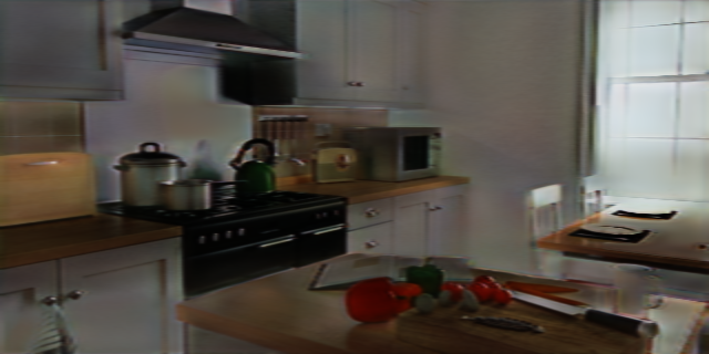
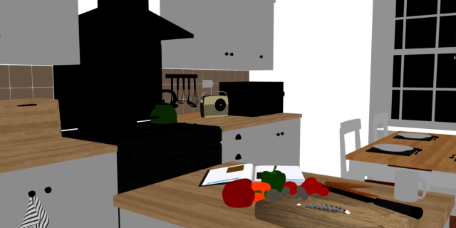
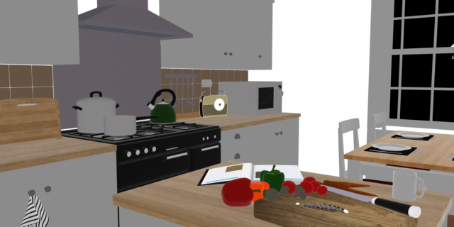
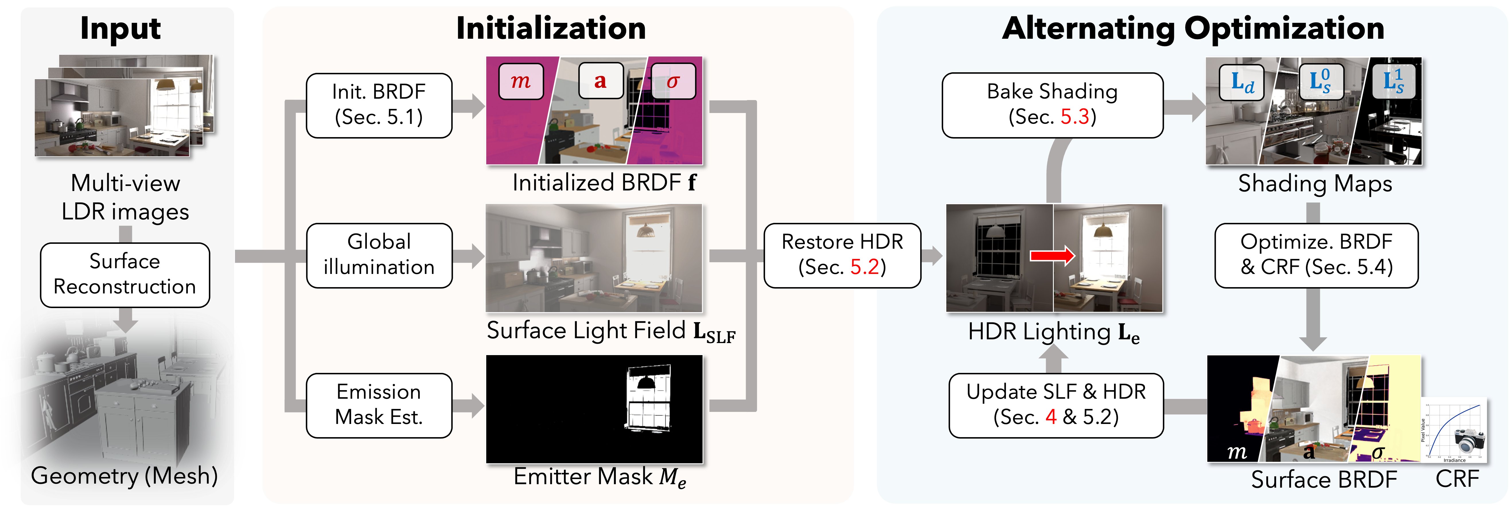
In response, we introduce IRIS, an inverse rendering framework that recovers the physically based material, spatially-varying HDR lighting, and camera response functions from multi-view, low-dynamic-range (LDR) images.
By eliminating the dependence on HDR input, we make inverse rendering technology more accessible.
We evaluate our approach on real-world and synthetic scenes and compare it with state-of-the-art methods.
Our results show that IRIS effectively recovers HDR lighting, accurate material, and plausible camera response functions, supporting photorealistic relighting and object insertion.